For complete and detailed information about the emPowerR3, download the user manual (wiring plans at page 11).
1.One pagers
Use this section for a quick overview of all the critical information about the emPowerR3. For more wiring diagram examples, see the user manual.
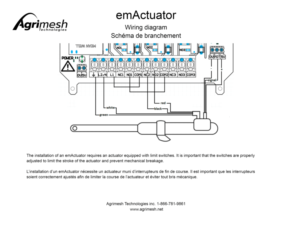
1.1 – emActuator
For detailed information about the emActuator, see its article.
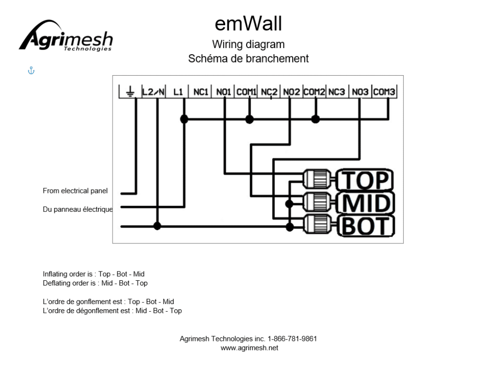
1.2 – emWall
2.Description
2.1 – emPowerR3
The AgriMesh emPowerR3 is a wireless control device controlling 3 relay outputs. It must be used in communion with an AgriMesh emHub system so that it can be used.
Each of the relay outputs can be used at a maximum voltage of 240 volts and a maximum current of 15 amperes. If used for motors the maximum load per relay and from 0.5HP to 120V and 1HP to 240V.
The device is protected against over-voltage and over-consumption.
2.2 – Related devices
Devices most commonly controlled by an emPowerR3 are light units, heaters, feeders and fans. With a particular wiring, it is also possible to control an actuator or an inflatable wall.
3.Troubleshoot
3.1 – Power related issue
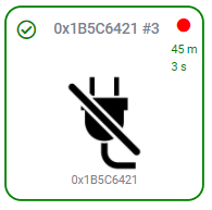
When a device controlled by an emPowerR3 stops working, the most common reason for this to happen is that there is no power supplying the Agrimesh box (and no power for the device). In this case, on the Agrimesh Console, you would see a red dot at the top right of the device. The timer below would indicate the time since the last communication was sent to the Hub. In this case, it is also the elapsed time since the device was last powered.
Most of the time, flipping the breaker restores the power to the device.
3.2 – No control from the Agrimesh Console
Most often, this occures soon after the electrician has installed the Agrimesh box. When triggering the relay manually using the test buttons in the box, the connected device will turn on. However, turning the device on or off from the Agrimesh Console will have no effect.
First, let’s diagnose the communication between the Hub and the emPowerR3. From the advanced information device page, sufficient communication will imply:
- TX RSSI signal between -10 and 0,
- RX RSSI signal between -75 and -40,
- A delay refreshing under 2 minutes 30 seconds.
Inadequate communication
If the device data does not match these values, communication between the Hub and the Agrimesh box should be improved. A few points to keep in mind in doing so:
- Try to make sure there are no thick concrete or metal structures in the way. They tend to weaken the signal quite significantly. If there must be, try adding at least one Agrimesh box – one with an emMesh – that has a clear sight of both the emPowerR3 and the Hub. It will serve as a relay.
- Stay as far awar as possible from electrical rooms. They tend to cause interference.
- If the emPowerR3 has a bad TX RSSI or RX RSSI when it is close by the Hub (less than a meter away), please contact our support.
Adequate communication
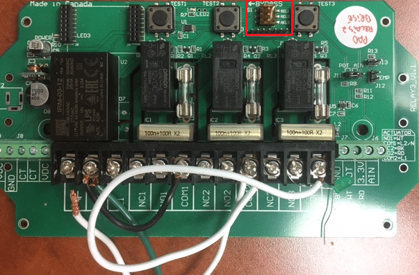
If the communication data do match all of the values mentioned earlier, then we can dispose of the communication issue. Some boards have a bypass feature that allows to have an external on/off switch. If this is the case, these bypass switches should always be towards the right (towards the third relay). Not all emPowerR3 have these switches.
3.3 – Configured device never powers on in automatic but works in manual mode
This one is most likely to happen after a particular device has been replaced, although it could happen at any point in time.
So you have went over the configuration for device and everything looks fine. Fans have their cfm configured, heaters have their btu’s entered. emActuators have their minimum and maximum setup with regards to the limit switches and emWalls have the appropriate inflate and deflate timers. Still, the device is just not being used.
The most common reason for this to happen is that the device is not configured in the room manager. In other words, the room manager doesn’t know that the device exists and is available.* To configure the device, follow these steps:
- In the Agrimesh Console, go to the main page (click the Agrimesh logo in the green ribbon),
- Select the room in which the device operates,
- Find the blue cog under the green rectangles, to the right,
- Select, in the menu at the top, what kind of device you want the manager to control,
- Check the particular device(s) that must be controlled in this room.
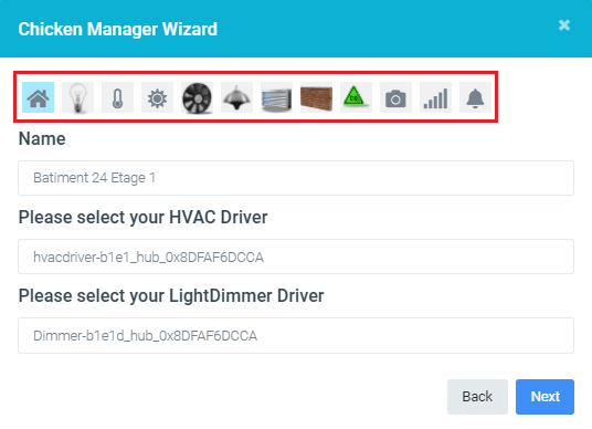
In the red rectangle below are the different icons for device types. Devices for each section will appear underneath.
*You can imagine that you have a bunch of tools and that you are the manager (or the user) of those tools. Now imagine a friend added the best tool possible to your toolset but didn’t tell you where it is. The chance of you using this tool, however good it is, is zero. This is why we must tell the room manager where to find the device it is going to use.
3.4 – Once the device is turned on, it does not power off unless the power is cut off
The following solution will only work if an external contactor is used. Below you will find two distinct solutions for the emDriveR and the emDriveRZ. To discriminate an emDriveR from an emDriveRZ, see type of the device.
Issue:
If the only way to turn off a device is by manually turning off the breaker, then the Agrimesh system cannot reliably use that device. It will always be on. The chart below shows how the device is maintained on by the contactor.
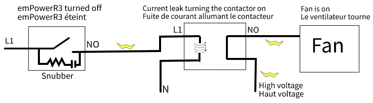
Even though the current is cut off in the relay, current leaks through the snubber and this leak is sufficient to trigger the contactor. In this manner, the device (a fan, for example) will stay on. Shutting off the breaker of a relay of the emDriveR will eliminate the leak and the contactor will turn off the fan.
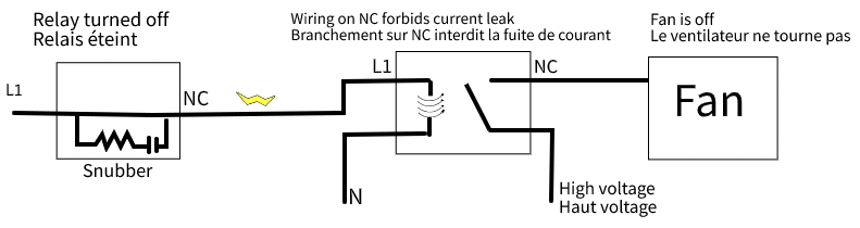
Solution for an emDriveR:
There is a way to fix this issue without having to buy any other parts. Rewiring through the normally closed (NC) on both the relay and the contactor instead of the normally open (NO) will make it so there is no leak of current. Also, the state of the device will remain the same as what is expected from the relay on the emDriveR.
Solution for emDriveRZ:
emDriveRZ have been redesigned partly to address this issue. There is a simple way to fix this issue: it is possible to remove the jumper on the board. This will eliminate the current from leaking into the contactor without having to work on the wiring again.
Below is the location of the jumper that should be removed off the board. Gently pull them out.
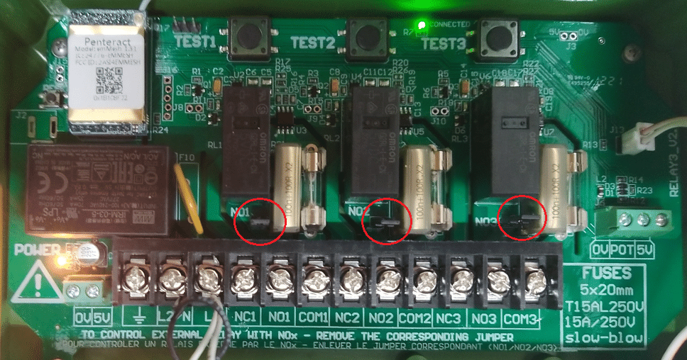
IF NO1 CONTROLS AN EXTERNAL RELAY OR A CONTACTOR : REMOVE JUMPER NO1
IF NO2 CONTROLS AN EXTERNAL RELAY OR A CONTACTOR : REMOVE JUMPER NO2
IF NO3 CONTROLS AN EXTERNAL RELAY OR A CONTACTOR : REMOVE JUMPER NO3
The relays on the circuit board are protected by a snubber, this will stop a power surge from frying the relays. ONLY in the situation where all the current is flowing through an outside contactor should it be removed. The snubber lets a small current flow through the NO output. This small current (around 50 mA) is sometimes enough to activate a contactor. By removing the jumper, we remove the link to the snubber. If all the current is flowing through an outside contactor, the internal relays do not need the snubber protection.